
Its algorithm would look like what is shown in Figure 2. For example, you can build a moving average filter by calculating the average of the last 10 input values. In practical words, a FIR filter takes the N previous input samples and uses them to calculate the next output value (see Figure 1a). As indicated by the article title, this type of FIR filter has a finite “memory” over time. The simplest one uses the FIR filter presented in my 207 article. However, as an efficient time machine has yet to be invented, at a given time step, a real-time digital filter must calculate the next output value based only on older values. As we live in a digital world, this data flow is a discrete-time signal (i.e., its successive values represent the signal value at discrete time steps). A digital filter is a piece of software, firmware, or logic circuit that takes a digital data flow as an input and provides a filtered version of this signal on its output. In this article, I will use the much-loved “soldering iron language” to show that IIR filters are similar to classic analog filters. One of the difficult things about IIR filters is that they are usually presented through exotic mathematical concepts (e.g., poles and zeros placement, Z-transforms, etc.) While these methods are invaluable, I want to explain the basics of IIR filters using simple words, math, and electronic concepts. Time has passed, and now I will try to fulfill your requests. I found it difficult to present IIR filters in a short article, probably because I was not familiar enough with them. Two of you asked me to write something about the other kind of digital filters-the so-called infinite impulse response (IIR) filters. I received five or six e-mails after it was published. My second Darker Side article was about finite impulse response (FIR) digital filters (“No Fear with FIR: Put a FIR Filter to Work,” Circuit Cellar 207, 2007). Over these five years, the great feedback and e-mail discussions with you, Circuit Cellar readers, have motivated me to continue! Moreover, my article topics are often inspired by readers’ comments. I am delighted to still be in front of my keyboard five years later. At that time, I thought I would have interesting electronics engineering topics to share with you for a year, maybe two.


I started this column in August 2007 (“Let’s Play with EMI!,” Circuit Cellar, 205).

written by: Dhidik PrastiyantoĢ.Hello, all. The script will show input signal and output signal of LPF which just been implemented. Let we plot the input and output of this filter. To apply filltering to the signal, we could write the following code: Fifth parameter is error vector whic is used only in chebisev and elliptic technique Fourth parameter is cut of frequency in normalization form It is also availabe other methods such as cheb1, chep2 dan ellip. Third parameter is technique which is used to design. Second parameter is filter type which lp= lowpass, hp=highpass, bp=bandpass. We could use higher order filter but please remberber taht higher order filter increase the number of calculation iterations. The normalization of 5Hz is 0.005 and 50 Hz is 0.05. In this case we select the frequency beetween signal and noise. Using Scilab, we can use available technique to design the filter such as Butterworth, Chebisev and elliptic.ĭeciding the cut of frequency is very easy by looking at freuency of signal and noise.
#SCILAB FIR FILTER DESIGN HOW TO#
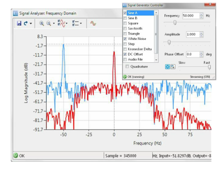
The important note is how to decide the cutt off frequency of the system. To seperate the signal from noise, we could use low pass filter. The noise is sinusoidal signal 50 Hz which also has 4 seconds time. Original signal is sinusoidal signal 5 Hz for 4 seconds. The following will be simulated noise cancellation using generated signal. Band Rejection: reject signal starting from cut off frequency 1 to cut of frequency 2.įilter coud be used to get the desired signal for example when EKG signal is disturbed by noise wich has lower frequensi signal. High Pass Filter (HPF): admit the signal over the cut of frequency Band Pass FIlter (BPF): pass signal from cut off frequency fc1 to cut of frequency fc2 Low Pass Filter (LPF): allow signal which as lower frequency than the cut off frequency. As we know that base on frequency respon filter could be classified into: In this article i would like to explain how to design filter using signal processing tool in Scilab. AS open source software, we could participate to develop the library of this software.
#SCILAB FIR FILTER DESIGN SOFTWARE#
The software could be download freely from scilab website. Scilab is an open source software for numerical computation.


 0 kommentar(er)
